In industrial liquid management, the question of how to maintain consistent fluid levels under high-pressure conditions without relying on external power sources is a practical one with real operational consequences. Facilities that handle water treatment, chemical storage, boiler feed systems, and pressurized tank filling regularly contend with pressure differentials that standard float valves cannot manage reliably. When a float valve fails under pressure, the result is not just an inconvenience — it can mean overflow, process interruption, equipment damage, or compromised safety conditions.
The challenge is not simply about pressure tolerance. It is about maintaining proportional, mechanical control over flow without introducing electrical components into environments where those components may be unreliable, hazardous, or simply unavailable. This is the operational context in which pilot operated float valve systems were developed and refined, and it remains the reason they continue to be specified across a wide range of industries today.
Table of Contents
What a Pilot Operated Ball Float Valve Actually Does
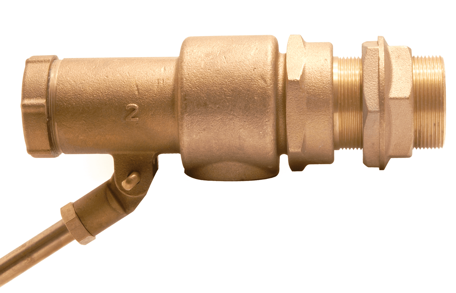
A pilot operated ball float valve is a mechanical flow control device that uses a small pilot valve — activated by the position of a float ball — to manage the opening and closing of a larger main valve body. Rather than asking a single float mechanism to carry the full force required to shut off high-pressure flow, the system separates the sensing function from the shutoff function. The float ball rises and falls with the liquid level, but it controls only a small pilot valve. That pilot valve, in turn, uses the line pressure itself to drive the main valve open or closed.
This separation of duties is the fundamental reason pilot operated designs handle high-pressure systems more effectively than direct-acting float valves. In a direct-acting float valve, the float arm must physically overcome the full line pressure to close the valve. At elevated pressures, this becomes mechanically impractical and leads to premature wear, incomplete shutoff, or failure to close at all. The pilot operated configuration removes that burden from the float entirely.
How Line Pressure Becomes the Closing Force
The mechanism by which a pilot operated system closes the main valve is counterintuitive until you understand how pressure is being redirected. When the float rises to the target liquid level, the pilot valve opens a small passage that allows upstream line pressure to act on the main valve’s diaphragm or piston from above. Because the surface area above the main valve element is larger than the inlet orifice area, the pressure force pushing down exceeds the pressure force pushing up, and the valve closes without any mechanical load on the float arm.
When the liquid level drops, the float falls, the pilot valve shifts position, the pressure above the main valve diaphragm is relieved, and the inlet pressure drives the main valve open again. The float arm and ball are doing very little mechanical work throughout this cycle. They are acting as a sensor rather than as a shutoff mechanism. This distinction matters in high-pressure systems because it means the valve can close fully and reliably across a wide pressure range without depending on float buoyancy to overpower the system.
The Role of the Ball Float in the System
The float ball itself has a specific role that is sometimes misunderstood. It is not simply a buoyant object attached to a lever — it is the primary sensing element of the entire control system. Its position determines when the pilot valve opens and closes, which in turn determines when the main valve responds. For this reason, the material, size, and surface integrity of the float ball are important to system performance.
In corrosive or high-temperature liquid environments, float balls made from stainless steel or other resistant alloys maintain their shape and buoyancy characteristics over time in ways that plastic or hollow carbon steel alternatives cannot. A float ball that deforms, develops a leak, or changes its buoyancy behavior due to material degradation will cause the pilot valve to receive inaccurate signals — leading to erratic liquid levels, short-cycling, or failure to close at the correct point. The float ball’s condition is directly tied to the precision of the entire assembly.
Why This Design Works Without Electrical Components
The pilot operated float valve system is entirely self-contained and mechanically driven. It requires no power supply, no solenoid, no control panel, no sensor wiring, and no external signal. All of the energy needed to open and close the main valve comes from the pressure already present in the supply line. This makes the valve functional in locations where electrical infrastructure is absent, impractical, or prohibited due to hazardous area classifications.
According to standards maintained by bodies such as the International Organization for Standardization, industrial fluid control components intended for use in pressurized systems must meet defined criteria for pressure rating, material compatibility, and mechanical reliability. Pilot operated float valves that meet these criteria offer a verifiable performance baseline that facilities can specify and audit without ambiguity. This matters in regulated industries where documentation of control system reliability is part of compliance.
Reliability in Remote or Unmanned Installations
One of the practical advantages of removing electrical dependency from a flow control valve is what it means for remote installations. Water storage tanks at rural sites, pressure break tanks in high-rise building systems, cooling tower feed lines, and agricultural reservoir inlets all share a common characteristic: they are frequently located where routine human oversight is limited and where electrical supply may be unreliable or nonexistent.
In these settings, a valve that depends on a float switch triggering a solenoid valve introduces multiple potential failure points — the switch, the solenoid, the wiring, the power supply. Each component in that chain can fail independently. A pilot operated ball float valve eliminates that chain entirely. The valve operates as long as there is liquid in the system and pressure in the supply line. There are no components waiting to fail due to a power surge, moisture ingress into a control cabinet, or a corroded terminal connection.
Performance Across Variable Pressure Conditions
High-pressure liquid systems are rarely static in their operating conditions. Supply pressure may fluctuate based on demand from other parts of the distribution network, pump cycling, or upstream storage conditions. A valve system that performs well under one pressure condition but becomes erratic as conditions change is a liability in an operational context.
Pilot operated designs respond proportionally to pressure variation. Because the closing force is derived from the line pressure itself, the valve’s holding force scales with the conditions it faces. When pressure rises, the force available to keep the valve closed also rises. When pressure drops, the valve continues to regulate based on float position. This inherent self-adjustment is not a programmed response — it is a mechanical consequence of the design, and it means operators do not need to recalibrate the valve every time system pressure shifts within its operating range.
Common Applications Where This Valve Is Specified
The pilot operated ball float valve appears across a range of industries specifically because of its ability to provide reliable level control where direct-acting valves would struggle and electrical systems would introduce unnecessary complexity or risk. Its applications are defined by the intersection of high pressure, liquid level management, and the need for long service intervals.
• Municipal and commercial water storage tanks where supply pressure is high and continuous operation is expected without regular maintenance intervention.
• Boiler feed water systems where both pressure and temperature conditions exceed the tolerance of standard float valves and where valve failure has immediate process consequences.
• Chemical storage and dosing tanks where corrosive liquids require float assemblies made from resistant materials such as stainless steel, and where electrical components near chemical atmospheres pose safety concerns.
• Cooling tower makeup water systems that run continuously and require reliable cutoff at a defined level to prevent overflow or pump cavitation from low-water conditions.
• Fire suppression storage tanks where the valve must function reliably during emergency conditions without depending on any powered infrastructure that may have been compromised.
• Agricultural and irrigation reservoirs that are filled periodically under pressure and are located far from any consistent electrical supply or regular operational oversight.
Maintenance Considerations That Support Long-Term Reliability
A pilot operated float valve system has fewer moving parts than an electrically actuated equivalent, but it is not maintenance-free. The components that most commonly require attention are the pilot valve seat, the main valve diaphragm or piston seal, and the float ball itself. Each of these has a wear or degradation timeline that depends on the liquid being handled, the pressure conditions, and the cycle frequency of the valve.
Pilot Valve Fouling and Its Operational Impact
The pilot valve handles a very small flow of liquid to shift the pressure above the main valve diaphragm. Because the passages involved are narrow, they are susceptible to fouling from sediment, mineral scale, or debris present in the liquid. If the pilot valve passage becomes partially blocked, the main valve may close slowly or incompletely, leading to liquid levels that overshoot their target and potentially cause overflow.
Inline strainers installed ahead of the pilot operated assembly are the most straightforward way to reduce this risk. They intercept particulate matter before it reaches the pilot valve, extending the interval between inspections significantly. Facilities that handle liquid with known sediment content should treat strainer maintenance as part of the valve maintenance schedule, not as a separate plumbing concern.
Float Ball Inspection and Its Effect on System Accuracy
The float ball should be inspected periodically for signs of denting, surface corrosion, or internal liquid ingress. A compromised float ball will sit lower in the liquid than it should, which causes the pilot valve to signal a lower liquid level than actually exists. The result is that the main valve remains open longer than intended, filling the tank beyond the set point before the float finally rises enough to trigger closure.
In stainless steel float balls, this degradation is slower and more predictable than in hollow plastic or carbon steel alternatives. Visual inspection during routine tank maintenance is usually sufficient to identify problems before they affect performance, particularly when the liquid environment is not highly aggressive.
Conclusion: Mechanical Simplicity as an Operational Advantage
The pilot operated ball float valve occupies a specific and well-defined role in industrial liquid management. It is not a universal solution for every flow control application, but in high-pressure systems where electrical infrastructure is absent, impractical, or undesirable, it provides a level of reliability that more complex control arrangements frequently cannot match.
Its strength comes from the way it uses the conditions of the system it serves — the line pressure — as the energy source for its own operation. This makes it inherently stable, responsive to real conditions, and free from the external dependencies that introduce failure risk in remote or demanding environments. The float ball senses. The pilot valve directs. The main valve acts. Each component does a defined job, and none of them require anything from outside the system to do it.
For facilities that prioritize long service intervals, minimal complexity, and consistent performance across variable pressure conditions, understanding how this valve type functions is a useful foundation for making sound specification and maintenance decisions. The mechanical logic behind it is straightforward, and that straightforwardness is precisely what makes it dependable over time.
-

-

-

-

-

-